Author Archives: admin

A comparison of Cushcraft A3S and Mosley PRO-96

On August 14, 2016 in the afternoon these two antennas were run against each other at SK0QO’s QTH on Gålö South of Stockholm. They were mounted on separate masts about 18 meters above the ground with water in front in a northwesterly direction. The test was done using the Reverse Beacon on 20m towards North America. The power was 100 watts.
Receiver          A3S dB SNR spots    PRO96 dB SNR spots
W1NT             11, 9                            9, 11
W3UA            19, 23                          16, 23
KM3T             19, 20                          17, 22
K1TTT            6                                   5

This gives that the A3S was on average 1.5 dB stronger than the PRO-96

EMC trouble with a “Home Studio”

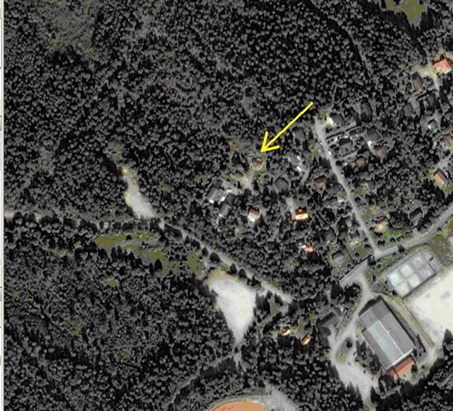
A neighbour bought a new “Receiver”, SONY STR – DN 1050 to his “home theater”. I was making a loud noise in his loudspeakers when I was transmitting. His old “Receiver” had no problem. The distance from the antennas is approximately 80 meters. Estimated field strength is well below 3 V / m which is, to my knowledge, the field strength a consumer equipment should withstand. The numbers are as usual not accessible to the man on the street. The disturbance was heard in ” surround speakers ” which had the longest lines.

In an attempt to cure the problem the speaker lines were wound with 5 turns in an FT 240-77 Ferrite core from Amidon . At the same time an extension cord with an equal core with 5 turns was connected between the wall outlet and all units. The disturbances remained, but had changed character. If the antenna was disconnected from the TV digital box, the disturbance disappeared. If a galvanic isolator coupled into the antenna line a weak disturbance remained (Note 1).

Upon contact with the SONY support their only advice was to reset the Receiver to factory settings. How that should be able to cure the problem, they could not explain.

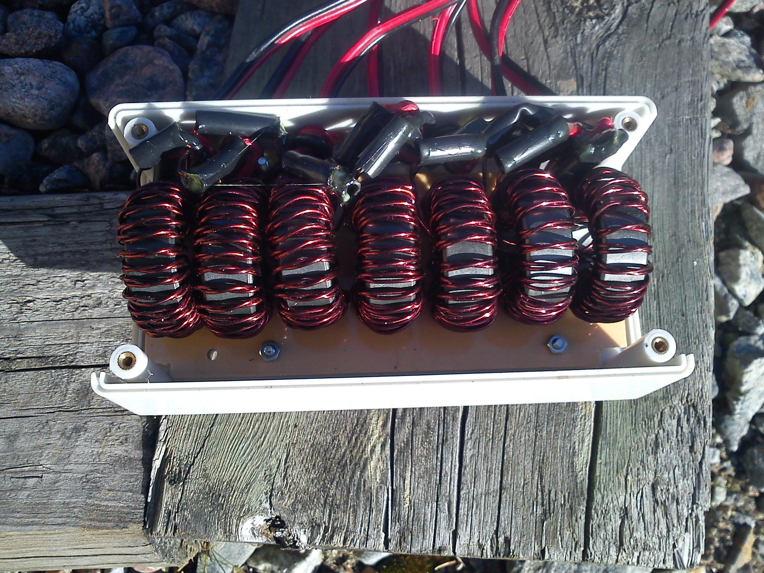
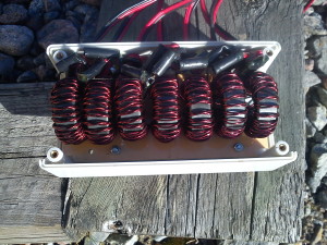
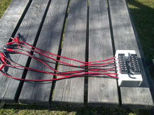
An EMC filter for common mode currents was made for the loudspeaker lines. It is made up of 7 FT-140-77 ferrite cores from Amidon. One for each loudspeaker. The Subwoofer is connected with a special line so it must be winded on a big FT-240-77 core.

DSC00583

DSC00587

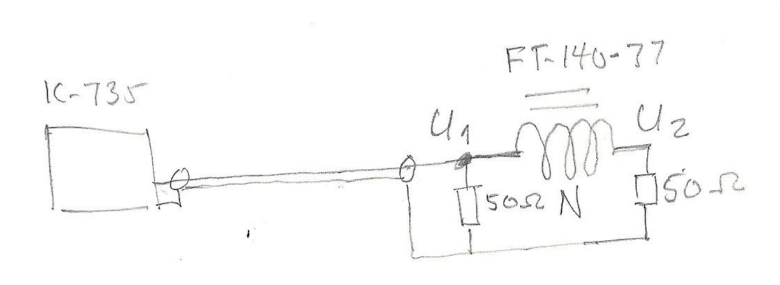
The attenuation on the different amateur band was measured.

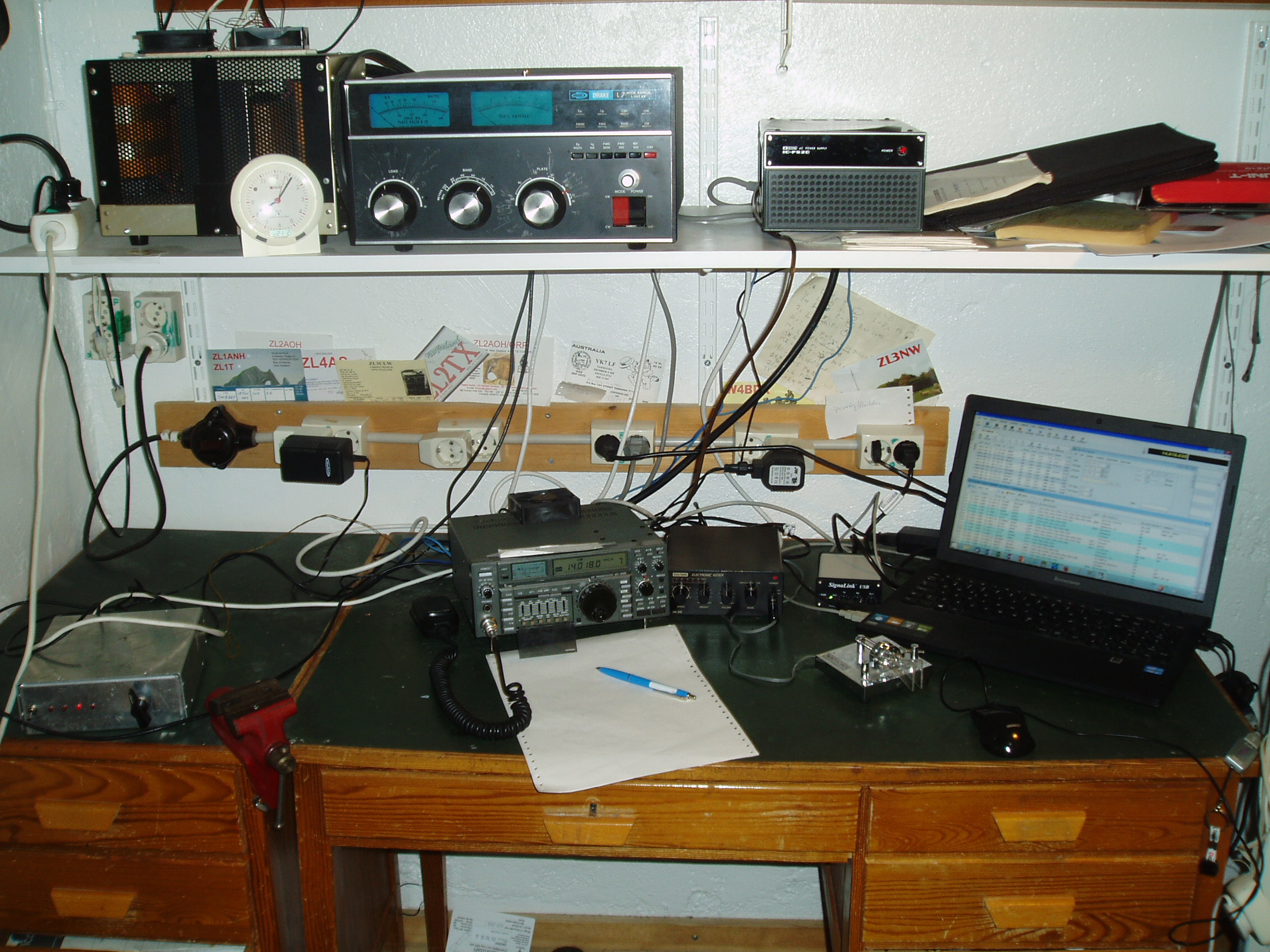
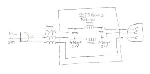
The measurements were made according to picture 1 below, with my IC-735 as a signal source.
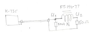
hogtalarfilter1

Pic.1


Results:

Frequency in MHz         U1 Volts pp                U2 Volts pp                Attenuation dB

1.8                                           37                                0.2                               46

3.5                                           38                                0.25                             44

7.0                                           37                                0.23                             42

10.1                                         38                                0.28                             43

14                                            38                                1.1                               31

18                                            34                                1.1                               30

21                                            30                                1.2                               28

24.9                                         25                                1.1                               27

28                                            23                                0.37                             36

In an effort to try to find a point with the lowest attenuation, the frequency was varied and also the impedance at U2. The lowest value found was 20 dBs at 25 MHz.


Note 1:

At a later point, it was discovered that the attenuation on shortwave for that thing was only 5 dBs. Therefore a new extension with a ferrite toroid with several turns was made.


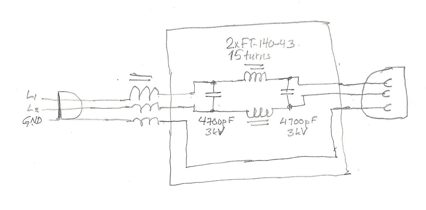
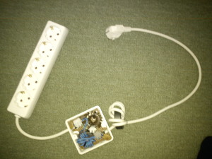
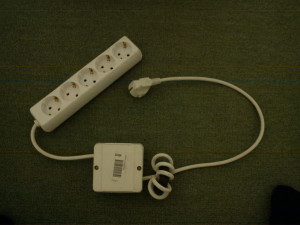
A line filter was made:
The power cord was winded 7 turns on a ferrite #33 core. 15 turns on line and neutral on a FT-140-43 core and 4700 pF ceramic capacitors.

Nätfilter1

DSC00953

DSC00952

DSC00956

Update Nov 17 2018:

I got a call from the neigbour where he said the noise was back in the loudspeaker. It totally blocked the sound from the TV set.

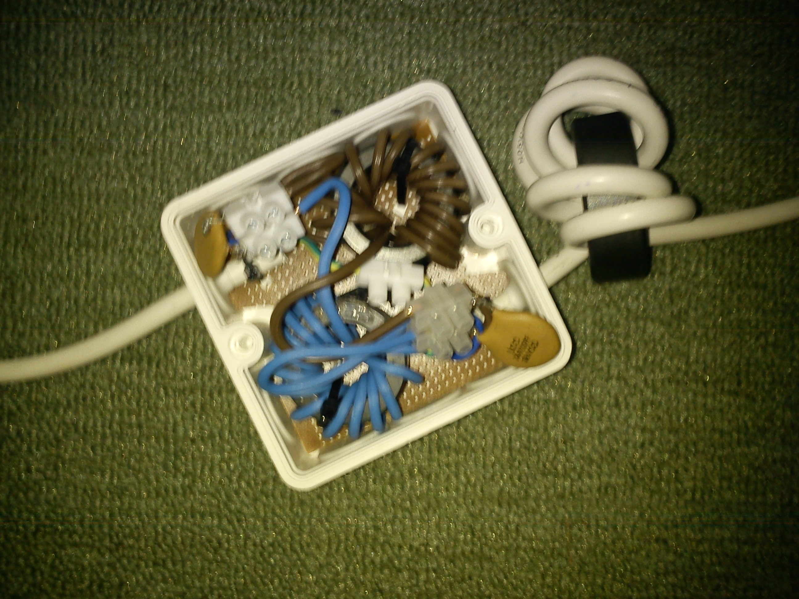
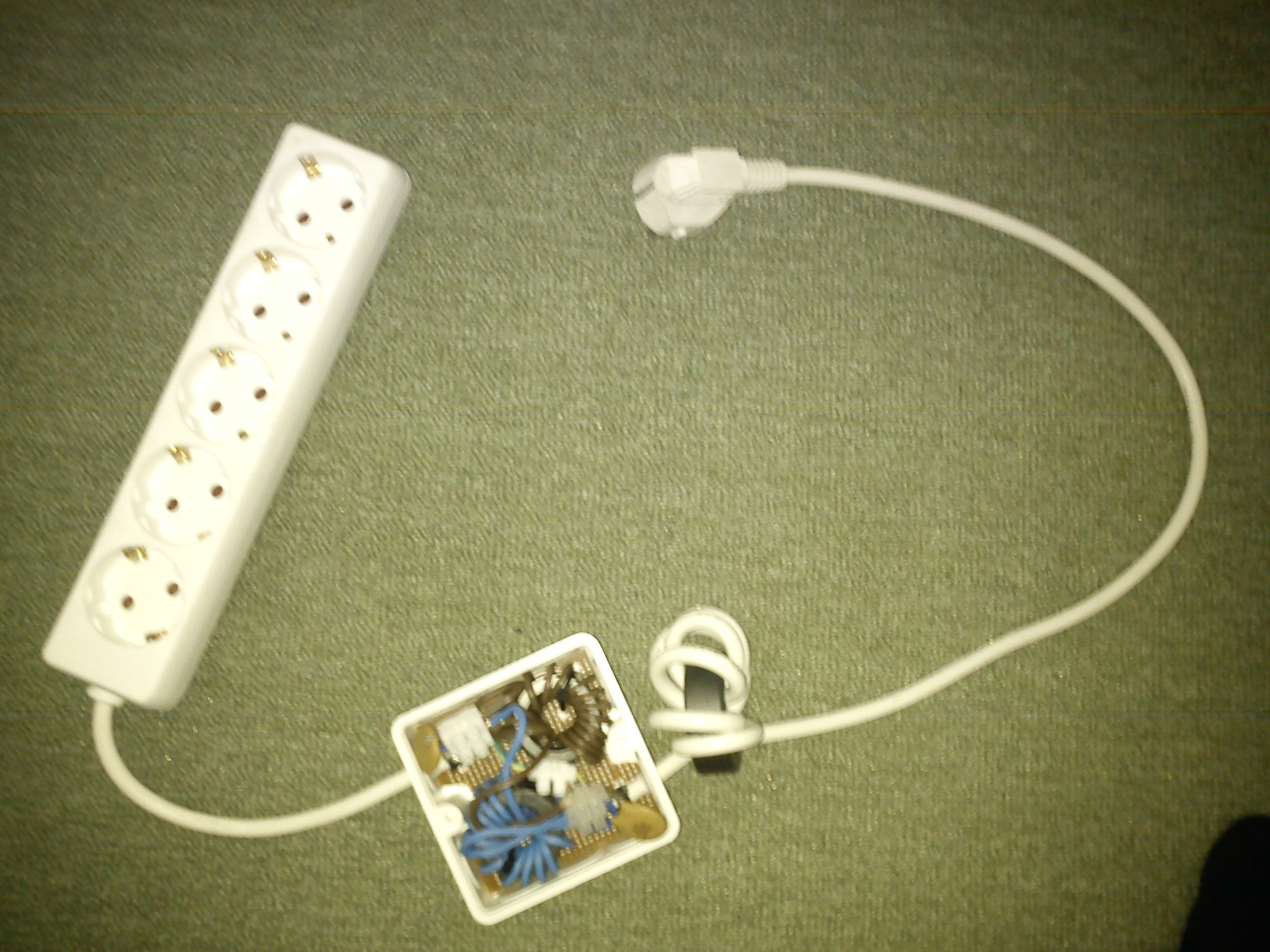
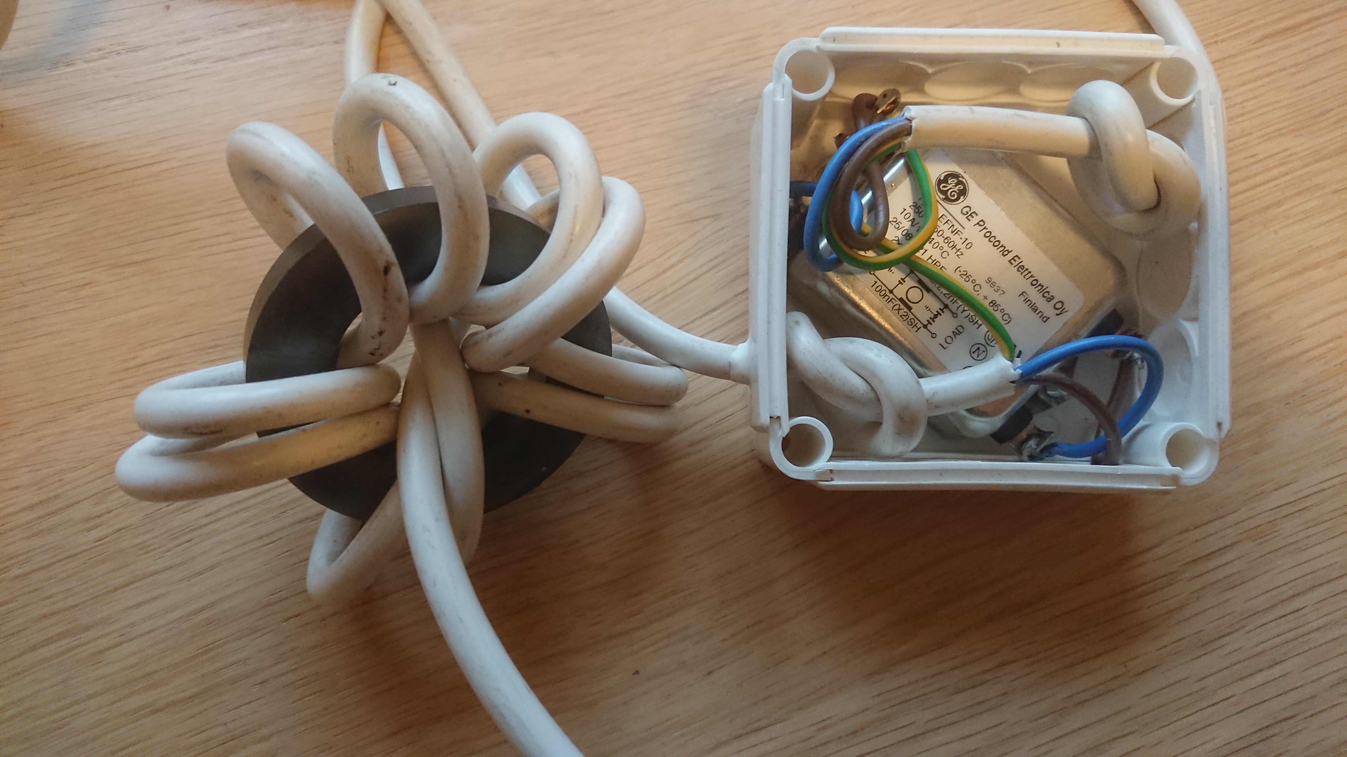
There was now a satellite box connected to the receiver.So the obvious reason for the new problem was RF entering the receiver’s HDMI outlet connected to the new box. An RF choke was made of RG-6 coax wound with about 8 turns through a FT 240 torroid core of #31 material. It was connected in series with the satellite box. The old power line filter was also changed with one from GE in a metal box. Idea was better resistance to fire if hit by a strong surge. Click to get enlarged picture:

It was also found out that the 7 line loudspeaker filter had never been installed. And that there had always been a low noise in the loudspeakers when I transmitted but it was so little he didn’t bother to connect it.

Today all filters were connected and no noise could be heard in the loudspeakers!


Interaction between the tribander and closely spaced dipoles for 30 and 40m

In order to find out the extent to which the dipoles for 30 and 40m affected the performance of the tribander, a FB-53, a number of measurements were performed. These were carried out in October 2014, and were limited mainly to the 20-meter band. The dipole was mounted about 50 cm below the tribander.

To perform the test I was using a reference dipole a few meters at the side of the beam when beaming North America and also a reference station with which there had been several measurement series over the years comparing the FB-53 Yagi with another tribander. On the average the FB-53 has been 2 dBs better than the other tribander towards North America during afternoons.

The comparisons were made by extensive number of Reverse Beacon spots from the North American East coast and averaging a large number.

The results can be summarized as follows:
With the 30/40m dipoles along the radiator of the tribander and the coax from the dipole shorted at the lower end

  1. -2 dB compared with the reference dipole.
  2. -3 dB compared with the reference station.

With the 30/40m dipoles along the radiator of the tribander and the coax from the dipole tuned at the lower end with a capacitor for SWR=1 on 20m

1. -3 dB compared with the reference dipole.(1 dB worse than shorted coax).
(It was possible to change the F / B ratio by shifting between the capacitor and short circuiting.)

With the 30/40m dipoles along the radiator of the tribander and the coax from the dipole connected to a 50 ohm dummy load at the lower end.
13% of the power fed to the tribander was dumped in the dummy load.

  1. 0 dB compared with the reference dipole.

With the 30/40m dipoles along the boom of the tribander

  1. +3 dBs compared with the reference dipole
  2. +2 dBs compared with the reference station. No interaction between antennas.

Conclusion

The proximity of the 30/40m dipoles to the tribander severely deteriorates the performance of the FB-53.

A second finding is that the gain of the FB-53 is 3 dBd on 20 m.


Does anybody want to join an effort to test reciprocity?

Would anybody be interested in exploring signal path reciprocity for shortwave communication? Or rather changes in reciprocity over time. It sometimes happens that for a period of time the path to a distant station seems to be more or less unidirectional. And I’m not talking about different noise levels but actual signal level.
The ionised plasma together with the Earth’s magnetic field will twist and deflect radio waves travelling through it making the path more or less non reciprocal.
I’ve been using WSPR to measure the reciprocity between SM and North America and it indicates that there at times could be a difference of up to 10 dBs. But there is a problem using WSPR. The output is not signal strength but SNR. On higher bands the QRN level is fairly constant over time, if not beaming into the sun, but there could be local noise or sudden QRM from say RTTY stations. At my end I’ve solved that by listening to a local station some tenths of km away and using that signal as a reference (the difference over a 24 hour period was very little). The DX station though did not use that feature.
The means of measuring the reciprocity is open to discussion.

Is there reciprocity?

Sometimes I experience a lack of reciprocity for the two directions of a connection. As an example it has happened in contacts with Japan at 17 m. During a period of about an hour, I have received several S-units better reports than I could give. Later, conditions have been leveled and more reasonable reports exchanged. Is it true or imaginary? And then meant “S-meter deflection” and not SNR, Signal to Noise Ratio.

To investigate the phenomenon I started a series of measurements using WSPR. An explanation of WSPR are in another post, but broadly it’s about that a station transmits its identity at different intervals and in between listening for other stations. The received stations are automatically logged with an indication of the SNR.

Actually, we want to have the absolute signal strength and not the SNR. However, I have found that the background noise in my location does not vary so much throughout the day on the higher bands from 20 m upwards. If one makes the bold assumption the same is true for most other stations, WSPR can be used to examine the reciprocity of the transmission path.

Typical back ground noise over 24 hours:

Bakgrundsbrus-over-dygnet

The measurements were performed during the end of the year 2013 and beginning of 2014.

I couldn’t demonstrate any systematic difference in propagation. However there were short periods of non reciprocity.

Below is an example of a series of measurements towards Japan on the 17 m band:

WSPR-SNR-17m-JA2KCT-1024x531

Towards the US on 20 m:

WSPR-2014-02-2526-20m-WA3DNM-diagram-1024x665

WSPR-2014-02-28-20m-WA3DNM-diagram-1024x948

Others have looked at this phenomenon earlier.

Tests have been carried out by Glen Davis Falcon vid Georgia Institute of Technology November, I960 och1956 av Laver, F.J.M. ; Stanesby, H. vid ”Post Office IngeneeringDepartment” UK:

” Tests have been carried out under carefully controlled conditions to see whether the attenuation of high-frequency signals sent over a given long-distance radio path differs according to the direction of transmission. The results obtained both across the North Atlantic and between Australia and the United Kingdom show that at times the loss in both directions is substantially the same, and that at other times the loss difference can rise to values of the order of 5 or 10 dB”.


Where am I?

I’m located in Huddinge 10km South of Stockholm City centre. It’s a very rocky and hilly terrain. Our house is on the South East end of a small hill stretching SE-NW with a plateau 150x20m wide 30m above the surroundings. Best direction is just south of east along an old sea bay, now filled with clay but stretching all the way out to the Baltic sea.

Scandinavia:

scandinavia

The Greater Stockholm Area:

huddingeoverview

A close up:

qthoverview

House and tower:

fromsouth