Author Archives: SM0BRF

Antenna for 40 m

The antenna for 40 m is a dipole inside two 12 m fiberglass poles from Spiderbeam. The outermost section is not used.  It is mounted just below the tribander at about 21m.

The 40 m dipole has been shown to have a negative impact on the FB 53 when oriented parallel to its radiator. It is therefore currently oriented along the boom of the tribander

See the post about the influence between different antennas.

My antenna for 10, 15 and 20 meters

UPDATE October 2017:

2017 October 15

Today the rebuilt radiator for the tribander was put in place. The traps were removed and there is now a full size dipole for 20 m made of aluminium from scrapped tubing. For 15 m there is a wire dipole erected 15 cm above the 20 m dipole and fed with a pair of copper wires. The dipole for 10 m is another 15 cm up and fed with 400 ohm ladder line. All dipoles are connected to the common original voltage balun from the FB-53.

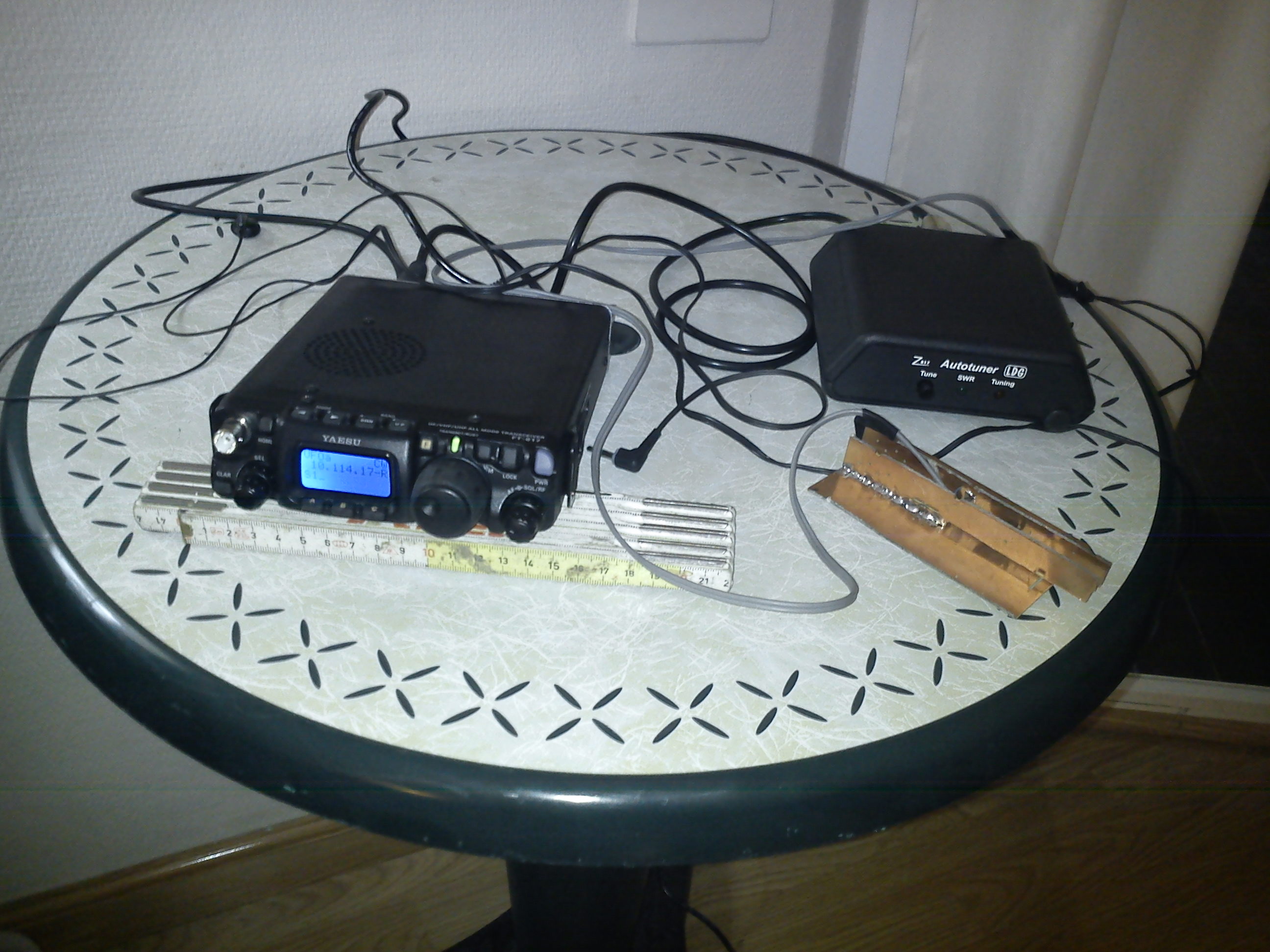
The whole device was adjusted for resonance at a height of about 5 meters with a MiniVNA PRO connected via Bluetooth to my Android phone.

When the radiator was in place it was swept from the shack with the length of the feeder (34.5 meters) removed. The most spectacular change was for the 20 m dipole. It was set for minimum SWR at about 14050 kHz. When in place in the beam the frequency for minimum SWR had moved to 14650 kHz and resonance was now at 14350 kHz. When I measured the length of the dipole at ground it was 2×5.0 m and not 2×5.2 m as I had simulated for a similar three element beam. But I didn’t believe it would change that much. The SWR is acceptable at the band edge so won’t take it down to change the length.

The 15 and 10 meter dipoles didn’t change that much but the overall SWR on 15 is on the high side all over the band.
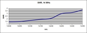
SWR numbers:

1.86:1 at 14000 kHz falling to 1.60:1 at 14350 kHz with a minimum of 1.44:1 at 14650 kHz

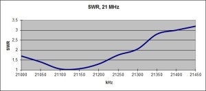
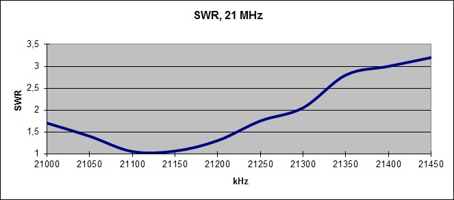
1.54:1 at 21000 kHz rising linearly to 3.10:1 at 21300 kHz

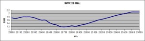
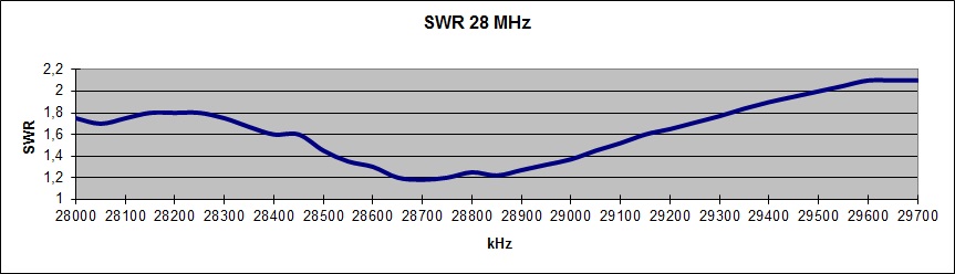
1.67:1 at 28000 kHz with a minimum of 1.56:1 at 28170 kHz and then rising to 2.20:1 at 28500 kHz.

I expect the gain of the beam on 20 to increase from the earlier measured figure of 3 dBd to about 4.2 dBd as a result of the “lossless” radiator.

The possible increase of output power to 1 kW due to the trapless radiator will give a boost of the signal with 1.5 dB on top.


Previous text:

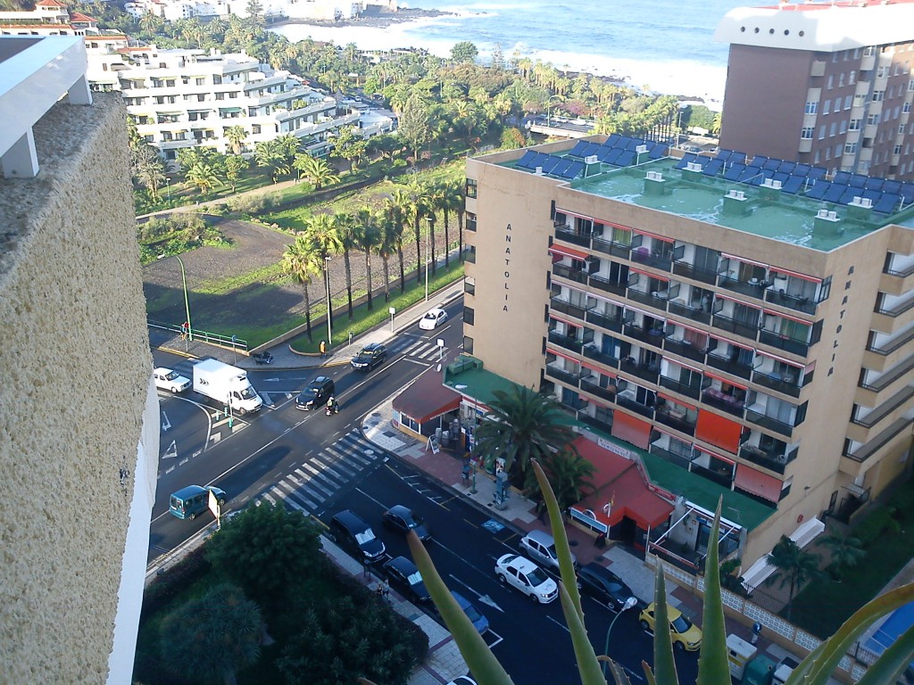
The antenna for 10, 15 and 20 meters, is a FB-53 tribander from Fritzel with 7.3 m boom length. It’s approximately 21.5 m above the ground.

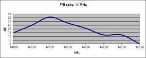
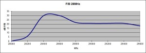
Measurement data for FB53 with the radiator and parasitic elements extended 2x3cm at  the ends. Resonance at 14 MHz lowered about 120 kHz:

  • The gain over a dipole on 20 m has been found to be about 3 dB on the CW portion. The measurement was made with a reference dipole and Reverse Beacon stations on the US East coast.
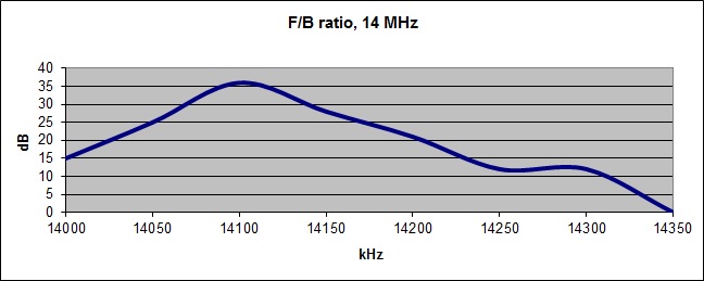
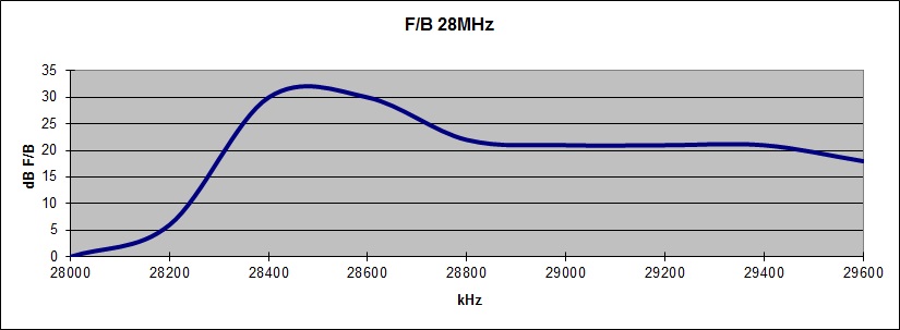
  • Standing wave and F/B ratios below.
    Measuring antenna was a delta loop at a distance of 100 m and height above the ground about 4 meters.

FB53FB20m

FB53_15m_FB-624x246

FB53FB10m

FB53SWR20m

FB53SWR15m

FB53SWR10m


Using WSPR to check reciprocity

WSPR ( Weak Signal Propagation Reporter ) is a mode created by K1JT ( Nobel Laureate
in Physics ) . The measurement results can be sent over the Internet to a common
server that presents the results in an Excel friendly format . The stations transmit 
and listen by turns and all results are uploaded . It may look like this . 
Signal / Noise level specified relates to a bandwidth of 2.5 kHz .

A travel to EA8 2014

In November 2014 XYL and I made a trip to Tenerife. I looked for a hotel with a good radio location and a room with “sea view”. The choice fell on hotel “Luabay” in Puerto de la Cruz. There was a free take off across the Atlantic Ocean from the Southwest to the Northeast.

The equipment was a FT 817nd with a small PS, an ATU, a manipulator of soldered copper laminate pieces and earpieces. The antenna was a wire along a 5 meter long telescopic fishing rod, an equally long counterpoise wire and a short wire with a powerful battery clamp for earthing to the balcony railing. The antenna was fed with 5 meters of RG-58 which was wound on a ferrite core at the antenna. The antenna pointed due west. The tuner managed to adjust the antenna system from 30 m to 15 m.

Most contacts were made with HAMs on the East Coast of the United States. Some were rag chew QSOs with QRP stations, having between 1 and 10 watts. But also numerous contacts with Europe, South America and the Caribbean. All contacts were made on CW.

DSC00122DSC00006-1024x768

I only had the antenna on the balcony when it was dark:

DSC00119

Below are some Reverse Beacon spots.

Good signals on 20m late at night at the end of November with 5W and a piece of wire.

At home in Stockholm the band closed when the sun sets early in the afternoon.

PJ2T  EA8/SM0BRF 14022.5 CW CQ 8 dB 17 wpm 2112z 28 Nov
K3MM  EA8/SM0BRF 14022.7 CW CQ 13 dB 17 wpm 2112z 28 Nov
WZ7I  EA8/SM0BRF 14022.6 CW CQ 15 dB 17 wpm 2111z 28 Nov
K3LR  EA8/SM0BRF 14022.7 CW CQ 26 dB 17 wpm 2110z 28 Nov
KM3T  EA8/SM0BRF 14022.5 CW CQ 24 dB 17 wpm 2110z 28 Nov
K2NNY  EA8/SM0BRF 14022.5 CW CQ 17 dB 17 wpm 2110z 28 Nov
W4KKN  EA8/SM0BRF 14022.6 CW CQ 17 dB 17 wpm 2110z 28 Nov
K8AZ  EA8/SM0BRF 14022.7 CW CQ 13 dB 17 wpm 2110z 28 Nov
DF4UE  EA8/SM0BRF 14022.6 CW CQ 11 dB 17 wpm 2109z 28 Nov
DK0TE  EA8/SM0BRF 14022.6 CW CQ 6 dB 17 wpm 2109z 28 Nov
PY1NB  EA8/SM0BRF 14058.1 CW CQ 11 dB 17 wpm 2057z 28 Nov
WZ7I  EA8/SM0BRF 14058.1 CW CQ 16 dB 17 wpm 2057z 28 Nov
K3LR  EA8/SM0BRF 14058.2 CW CQ 19 dB 17 wpm 2057z 28 Nov
K8AZ  EA8/SM0BRF 14058.3 CW CQ 14 dB 17 wpm 2057z 28 Nov
K1TTT  EA8/SM0BRF 14058.2 CW CQ 14 dB 17 wpm 2057z 28 Nov
KM3T  EA8/SM0BRF 14058.0 CW CQ 21 dB 17 wpm 2056z 28 Nov
NZ1U  EA8/SM0BRF 14058.2 CW CQ 15 dB 17 wpm 2056z 28 Nov


Antennas for 80m

For 80 meters there are two inverted vee dipoles with apexes 20 meters above ground. One is provided with a parasitic element, which can be configured either as a director or reflector. The directions are SW or NE.

The other one has one leg almost horizontal towards SW and the other leg is going down almost vertically with the end about 7 meters to the NW. One could call it an inverted L dipole.

Antennas for160 m

For 160 m the whole tower plus the top mast, around 28 m, is used with the Yagi antennas as a capacitive top load. The tower is supplied with Gamma Match and connected to a sparse radial system. Self-resonance is 2.2 MHz.

There is also a low dipole configured as an inv vee with top at 20m.