UPDATE October 2017:
2017 October 15
Today the rebuilt radiator for the tribander was put in place. The traps were removed and there is now a full size dipole for 20 m made of aluminium from scrapped tubing. For 15 m there is a wire dipole erected 15 cm above the 20 m dipole and fed with a pair of copper wires. The dipole for 10 m is another 15 cm up and fed with 400 ohm ladder line. All dipoles are connected to the common original voltage balun from the FB-53.
The whole device was adjusted for resonance at a height of about 5 meters with a MiniVNA PRO connected via Bluetooth to my Android phone.
When the radiator was in place it was swept from the shack with the length of the feeder (34.5 meters) removed. The most spectacular change was for the 20 m dipole. It was set for minimum SWR at about 14050 kHz. When in place in the beam the frequency for minimum SWR had moved to 14650 kHz and resonance was now at 14350 kHz. When I measured the length of the dipole at ground it was 2×5.0 m and not 2×5.2 m as I had simulated for a similar three element beam. But I didn’t believe it would change that much. The SWR is acceptable at the band edge so won’t take it down to change the length.
The 15 and 10 meter dipoles didn’t change that much but the overall SWR on 15 is on the high side all over the band.
SWR numbers:
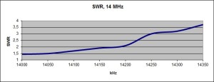
1.86:1 at 14000 kHz falling to 1.60:1 at 14350 kHz with a minimum of 1.44:1 at 14650 kHz
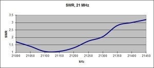
1.54:1 at 21000 kHz rising linearly to 3.10:1 at 21300 kHz
1.67:1 at 28000 kHz with a minimum of 1.56:1 at 28170 kHz and then rising to 2.20:1 at 28500 kHz.
I expect the gain of the beam on 20 to increase from the earlier measured figure of 3 dBd to about 4.2 dBd as a result of the “lossless” radiator.
The possible increase of output power to 1 kW due to the trapless radiator will give a boost of the signal with 1.5 dB on top.
Previous text:
The antenna for 10, 15 and 20 meters, is a FB-53 tribander from Fritzel with 7.3 m boom length. It’s approximately 21.5 m above the ground.
Measurement data for FB53 with the radiator and parasitic elements extended 2x3cm at the ends. Resonance at 14 MHz lowered about 120 kHz:
- The gain over a dipole on 20 m has been found to be about 3 dB on the CW portion. The measurement was made with a reference dipole and Reverse Beacon stations on the US East coast.
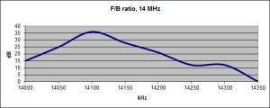
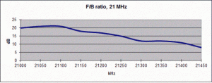
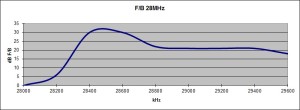
- Standing wave and F/B ratios below.
Measuring antenna was a delta loop at a distance of 100 m and height above the ground about 4 meters.

