A trip to Gran Canaria in December 2018

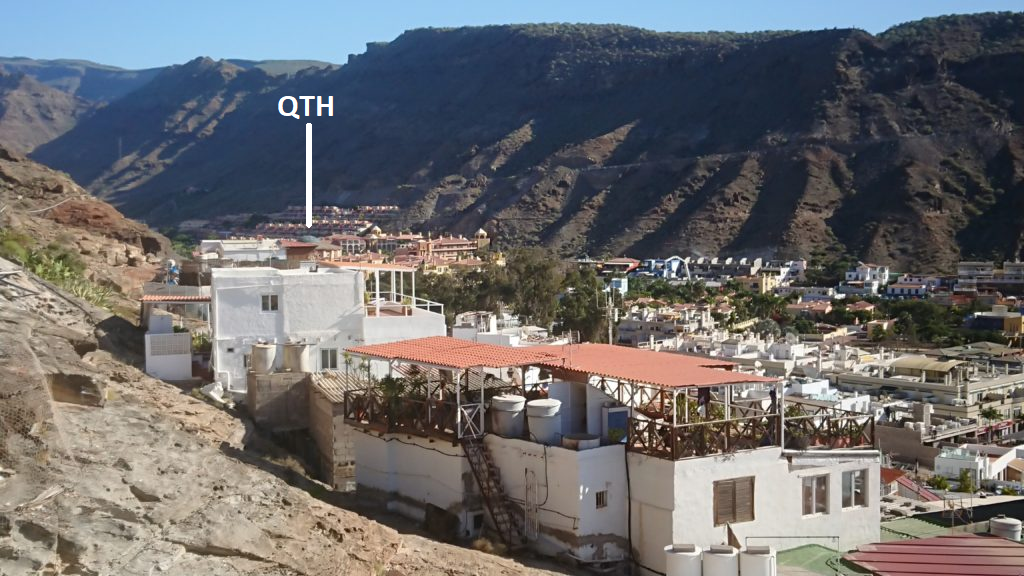
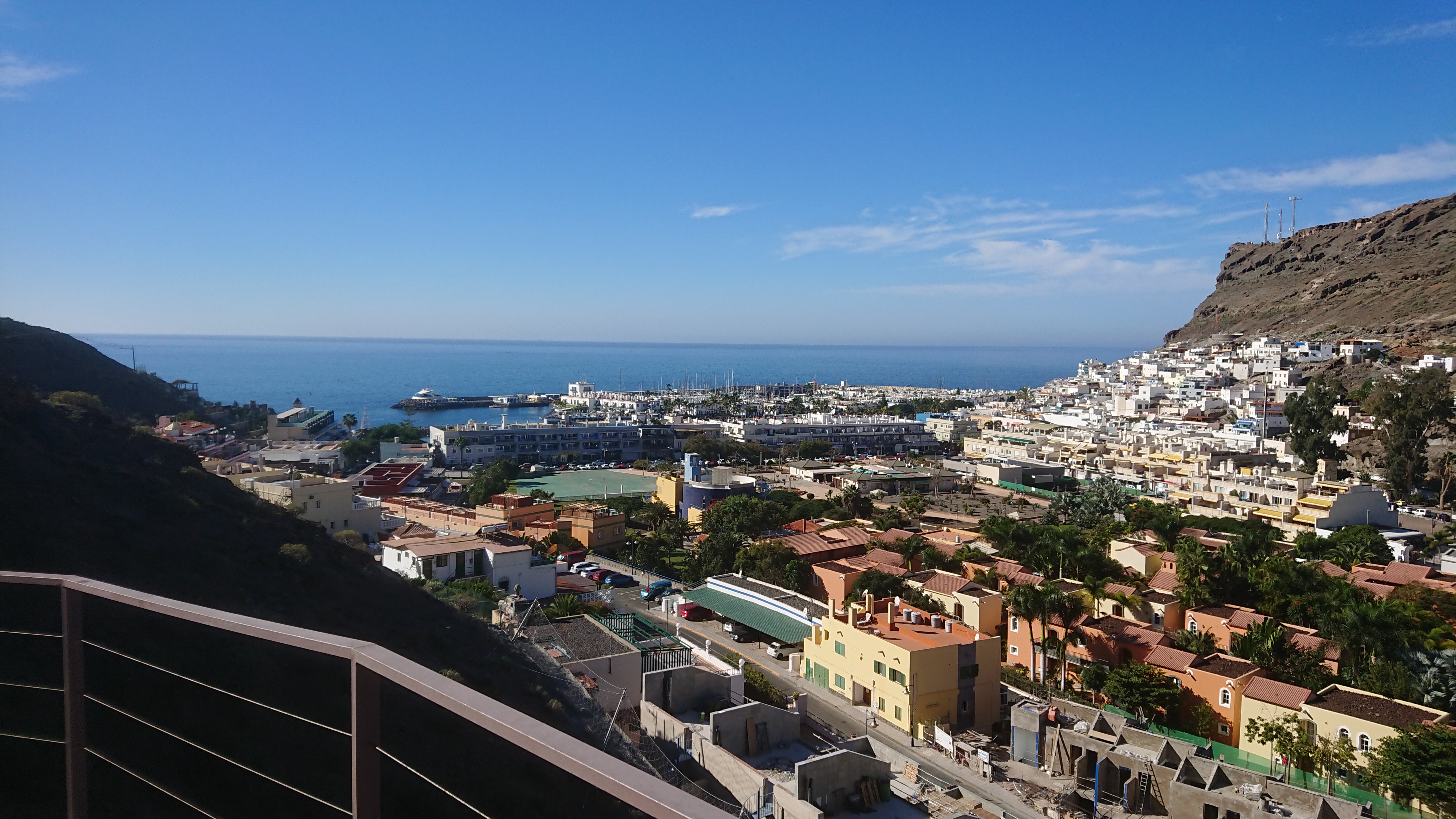
On December 8, 2018, XYL and I traveled to Puerto de Mogan on Gran Canaria. As usual, I brought my FT-817nd. We stayed at Cordial Mogan Playa Hotel, a few hundred meters up the ravine from the village. It was easy to predict that the QTH was not the best with high mountains all around except to the South-West. I checked the take-off angle using http://www.heywhatsthat.com/profiler.html and estimated it to 10 degrees. I judged that it would be possible to work from the bottom of the ravine after all. Once in place, the angle from the balcony to the surrounding mountain ridges were measured to 35 degrees to the west and approximately 60 degrees to the east. Against Europe, the angle was slightly lower than 35 degrees.


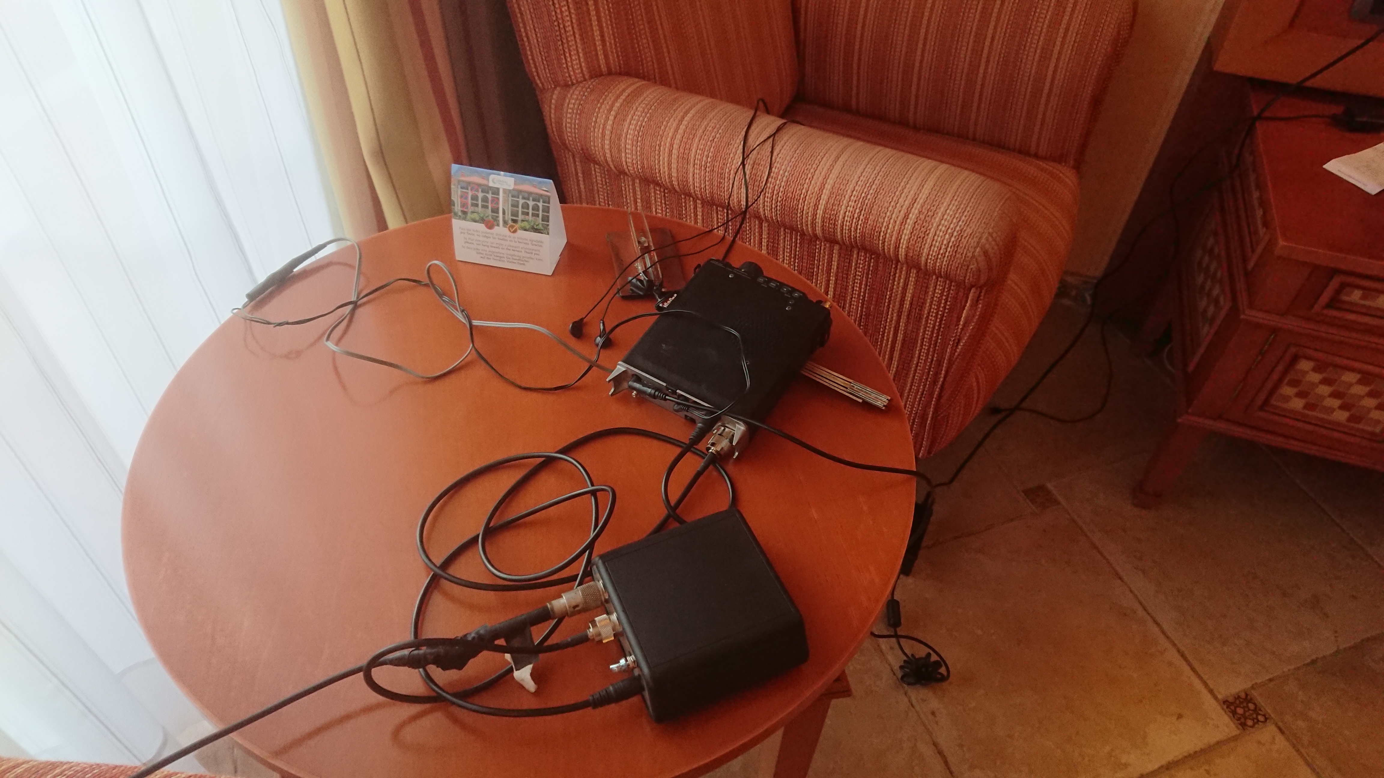
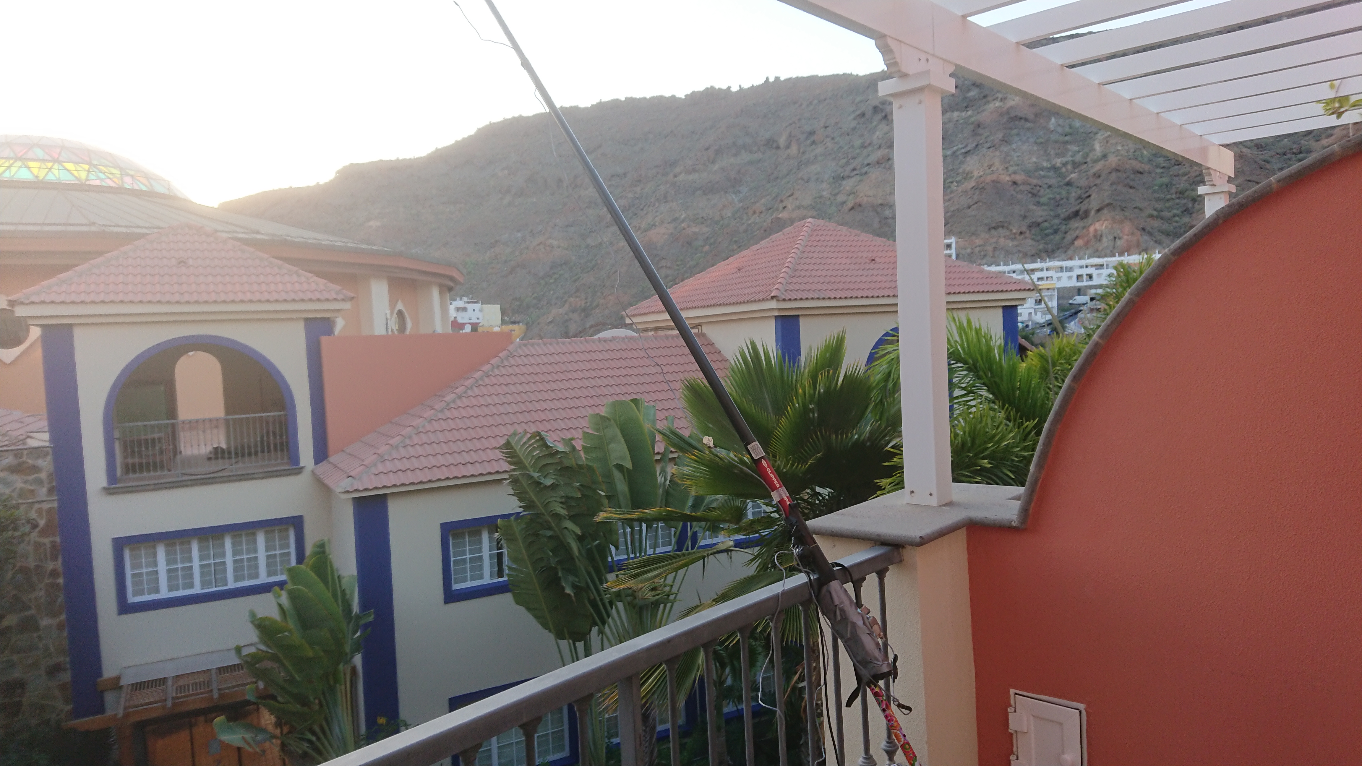
The fishing rod with 5 meters of antenna wire alongside was mounted on the balcony in the southwest direction and pointed upwards at 45 degrees. As a counterweight, the balcony’s steel rail was used. The ATU could match the antenna from the 30 to the 15 meter bands.


It turned out that all amateur bands from 20m upwards were completely dead. There was not even any atmospheric noise.


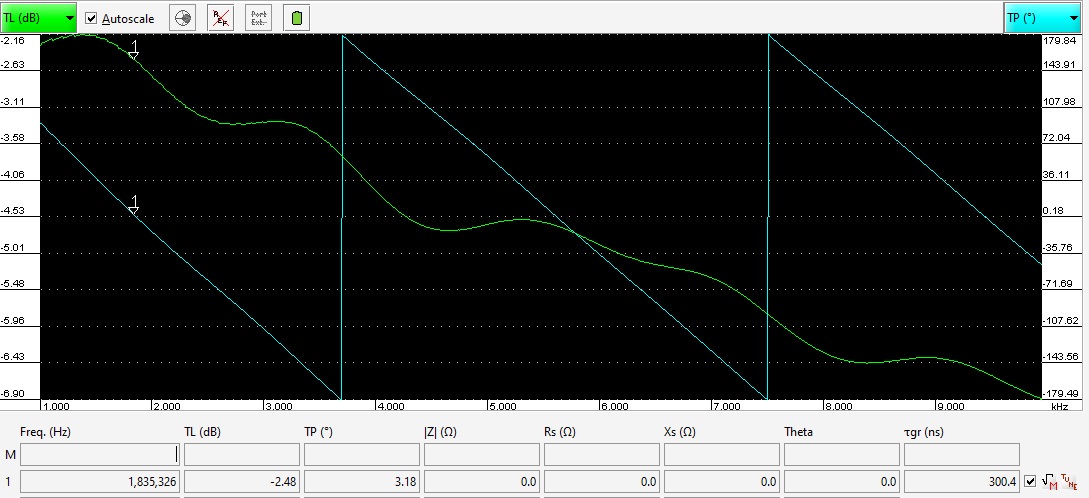
However, contacts were possible daily with Europe on 30 and 40 m from an hour before sunset for about 20 minutes. That was from about 1710 to 1730 local time and equal to GMT. The sunset was around 1810. It shows that the radiation angle at that time was very high. The signals probably entered at an angle of 30 degrees above the horizon or more. A very good indicator was the German weather station at 10100 kHz. It went from S0 on the meter to S8 for a few minutes and then quickly fell back again.


To be able to use 40 m, a 5 meter long extension of the antenna wire was connected from the tip of the fishing rod wire back to the other end of the balcony. It became a fairly pointed angle, but the ATU could match the extended antenna on 40, 30 and 20m.


Only EU stations were worked. PY stations were often heard, but they were weak.

What is e.i.r.p.

Effective Isotropic Radiated Power (e.i.r.p). What is it?

e.i.r.p. = Pout (from TX) – losses (in antenna and feeder etc) in dB + antenna gain in dBi.

The regulations for 5 MHz in Sweden with max 15 W e.i.r.p. will have some strange consequences:

An inverted vee dipole with apex at 13 m has a gain of 6.7 dBi. If losses in tuner and feedline amount to 1 dB, Pout should be 5.7 dBs lower than 15 W or 4 W. It holds for an antenna over even ground with average conductivity.

For a vertical ¼ wave GP with 2 to 4 radials at 2 m Pout max is rather 30W.

Click on the image for a better view.

Inv vee dipole at right angle to the antenna plane:                           Vertical:

Military telephone cable as the antenna wire. How big are the losses?

The DL-1000, which is the defense’s telephone wire, consists of 7 strands. 4 from copper and 3 galvanized steel wires and an insulating coating. It is popular as antenna wire. The question is how it stands against copper wire regarding losses on short wave.

The MMANA simulation program allows you to select materials in the antenna conductors. The difference in material losses between copper and steel wire amounts to more than 3 dB for a 20m dipole.

To make a practical measurement, a dipole for 14 MHz was mounted with the center 7 meters above ground and the ends one meter lower. A MINI VNA was connected to the 37 meter long RG 213 coaxial cable and the length was retracted. However, the cable is simulated as loss-free.

In addition to 1.5 square mm copper, 1 mm plastic coated soft steel wire was used, which is used in the garden.

The feed impedance was measured at the resonance point when it was pure resistive.

Results:

Impedance ohm

Copper         53

DL 1000        64.7

Steel wire     74.2

Thus, an additional loss resistance of 11.7 ohm for DL ​​1000 and 21.2 ohm for steel wire. This corresponds to 18% or 0.85 dB extra power loss for DL ​​1000 and 28.6% or 2.3 dB for the steel wire.

Additional information:

The DC resistance of a strand of DL1000 is 7 ohms/100m.

I have simulated what happens with an LW of 100 meters at 14 MHz:

When I measured a dipole, the feed impedance increased by about 12 ohms when I used the DL1000 instead of the FK 1.5. This means that a 12 ohm loss resistor is in series with the copper wire feed impedance. For steel wire, the corresponding loss resistance was 21 ohms.   I then put the corresponding loss resistance in all the current maxima on the long wire. One can see it as 10 series-connected half-wave dipoles.   The result was that a 100 meter long wire of 14 MHz with the DL1000 had 1.6 dB of lower gain than an LW of copper! For a half-wave dipole, the corresponding losses were 0.85 and 2.3 dB, respectively. The longer the antenna is, the more important with good material in the wire (and, of course, low losses in the ground).   In figures: Gain Cu = 10.7 dBi, Gain DL1000 = 9.13 dBi and Gain steel wire = 8.44 dBi. The latter result does not correspond to what you get if you choose steel as material in the antenna wire in MMANA. Then Gain = 7.1 dBi ie 3.63 dB worse than with copper. The same goes for half-wave dipoles.   By comparison, a 3 element monoband has a gain of about 12 to 13 dBi.    

If the antenna length is increased to 200 meters, the gain increases:
Gain Cu = 12.16 dBi, Gain DL1000 = 10.18 dBi ie an additional 1.43 (Cu) and 1.05 dB (DL1000) respectively. For steel wire the gain is then 8.1 dBi.

Below a 10 wavelength long wire 1 wavelength up on 14 MHz.
With Copper Line:


With (a half from) DL1000:

With steel wire:

My Beverage antennas

There are four bevs:

1. A 190 m terminated wire in 290 dgs. Works great for North America.

2. A 185 m teminated wire in 240 dgs.

3. A 130 m terminated wire in 60 dgs. Just a little bit better than number 2. Discriminates signals from SW with about 2 S-units. A bit disappointing.

4. A 120 m unterminated wire in 355 dgs.

Common mode measurement of DL1000 telephone cable.

I’ve been a bit sceptical about the balance of the military telephone cable called DL1000 in Sweden. It almost looks as if one wire is wound around the other rather than two twisted wires. So I made a measurement as outlined in the sketch below while listening on strong signals:

As reference I connected both wires in parallel connected directly to the measurement receiver.

The results were:

Frequency     Common mode rejection

7 MHz            25 dB

3.5 MHz         40 dB

There was no difference with and without the load resistor R.

So the telephone line is OK as a feeder for receiving antennas on 80 and below as regards to common mode pick up but doubtful on 40m.

Measuring attenuation of DL1000 military telephone cable.

I was using a 50m length of DL1000 telephone cable with a transformer with binocular BN73-202 at each end with a turn’s ratio of 2:3. There was a MINI VNA Pro used in transmission mode connected to the transformers.


Attenuation in the transformers:


Attenuation in transformers plus 50 m of DL1000 telephone cable:


Replacing the Beverage feeding system

I’m replacing my Beverage feeding system. The relays in the switchbox was powered through the feeder which was 40 m of buried RG-6 coax plus 70 m of military phone line in the trees. I had problems with noise from the relay voltages so now replacing it with buried outdoor UTP cable feeding the relays separated from the RF feeder.

The impedance of a UTP pair is 100 ohms and measured attenuation over 100 meters was as follows:

1.8 MHz                1.5 dBs

3.5 MHz                1.7 dBs

10.1 MHz             2.6 dBs

I took the transformers from the old 70 ohm system and measured the 50 ohm SWR all the way through 100 m UTP to a 560 ohm resistor in place of the Beverage wire:

The SWR was 1.35 at 1.8 MHz, 1.05 at 3.5 MHz and 1.55 at 10.1 MHz


Today Oct 4, the new beverage feeding system is up-and-running. Works as expected but the ground lead is too long picking up too much signal, especially on 40 and up. Had to move the relay unit from one tree to another. Will try to improve that.

Today November 8 I improved the ground with an extra ground stake. There is also a new NE wire running at 65 Dgs. It’s a 130 m long terminated wire.


Aurora and sporadic E

On 21st of December 2016 local K-index was 8 (with 9 as theoretical maximum) with severe aurora. Strange things happened. Sort of sporadic E (or maybe sporadic F) was formed by the strong radiation. So had a QSO with W9YXX in Indiana on 20, late in the evening with 599 signals. Normally the band closes early.  At such occasions the propagation is very patchy. I got a 31 dB RBN spot from WZ7I and a 27 dB spot from K3LR. No spot from anyone else in Europe or anywhere.  I was the only EU station heard at his end he was the only station heard here except for C91PA who was 59 on 20, SSB. The noise was virtually zero with the needle stuck at the bottom stop.

Part of the QSO with W9YXX:


So great fun in spite of non-existing normal propagation

Antennarbeten

2016-09-07

Tänkte prova 30m-tillsatsen för min A3WS. Den har legat och väntat i garaget i kanske 15 år. Filosofin har varit att passa på och montera den när det uppstod ett problem på beamen och jag skulle bli tvungen att ta ned den. Nu har ett fästband som hållit koaxen mot bommen gått av. Dags att agera.

Det visade sig bli ett större jobb än vad jag trott. För att kunna ta ned WARC-beamen måste jag ta ned min dipol för 40m och min trebandare FB-53. Jag tillverkade en linbana enligt tips på nätet. Det visade sig vara lättare sagt än gjort att få ned antennerna. Allting trasslar sig med allting och det som ska fungera i teorin har allvarliga brister när det kommer till verkligheten.

Idag har jag i alla fall fått ned 7 MHz-dipolen och FB-53an. Återstår A3WS.

2016-10-24

Efter ett par veckor sitter alla antenner på plats. 30-meterstillsatsen på WARC-beamen går förträffligt. 25 meters höjd verkar passa den bra.

FB-53an har sänkts i frekvens på 20 meter till 14070 kHz. I original ligger den på 14225 kHz. Det förbättrade SWR och F/B-förhållandet på CW-delen. Dessutom monterades 3 cm långa pinnar före trappsen på den närmsta 10/15-metersreflektorn för att försöka förbättra F/B-förhållandet på CW-delen på 10 meter, men det verkar inte ha haft någon större efekt.

Inför lågbandssäsongen har en 160-metersdipol hängts upp och ett parasitiskt element har satts parallellt med befintlig Invvee-dipol. Den antingen direktor eller reflektor genom att ändra längde ett par meter. Riktningarna är SV eller NO. Dessutom finns en inverted vee-dipol med bredsidan NV/SO.