En granne skaffade en ny “Receiver” av typen SONY STR-DN 1050 till sin “Hembioanläggning”. Jag hörs kraftigt i den vid sändning. En tidigare “Receiver” hade inte alls det problemet. Avståndet från antennerna är ungefär 80 meter. Uppskattad fältstyrka är klart under 3 V/m. Störningen hördes i “Surroundhögtalarna” dit de längsta kablarna gick. De högtalarkablarna lindades 5 varv i en FT-240-77 ferritkärna från Amidon. Samtidigt kopplades en skarvsladd in mellan vägguttag och samtliga enheter. Den var också lindad 5 varv på en likadan kärna. Störningarna var kvar, men hade ändrat karaktär. Vid prov att koppla från kabeln till TV-antennen försvann störningen. En kabel med en galvanisk isolator kopplades in i antennledningen (anm 1). Det återstod en svag störning. Vid kontakt med SONY support säger dom bara att receivern ska återställas till fabriksinställningarna. Hur det ska kunna få bort EMC-problemet har de inte kunnat förklara.
Ett filter för högtalarledningarna ska tillverkas.
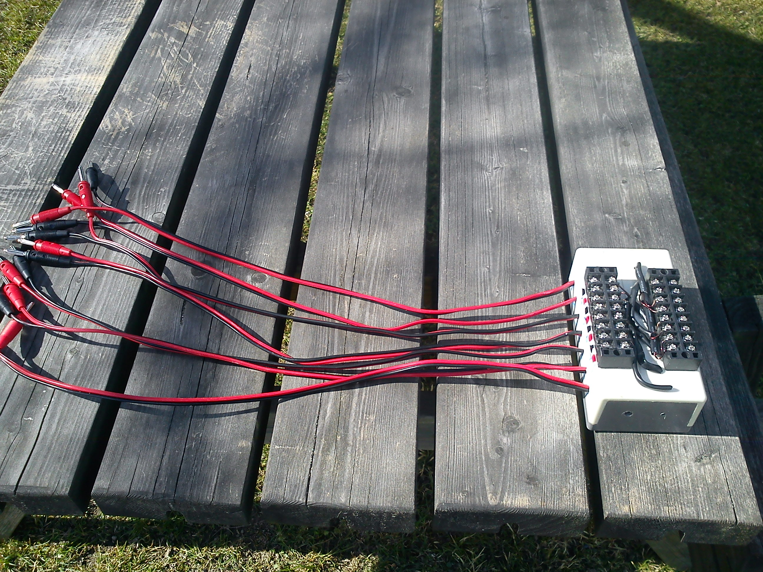
Mätningar gjordes på en koppling enligt figur 1.
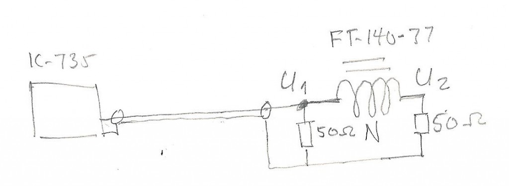
Fig.1
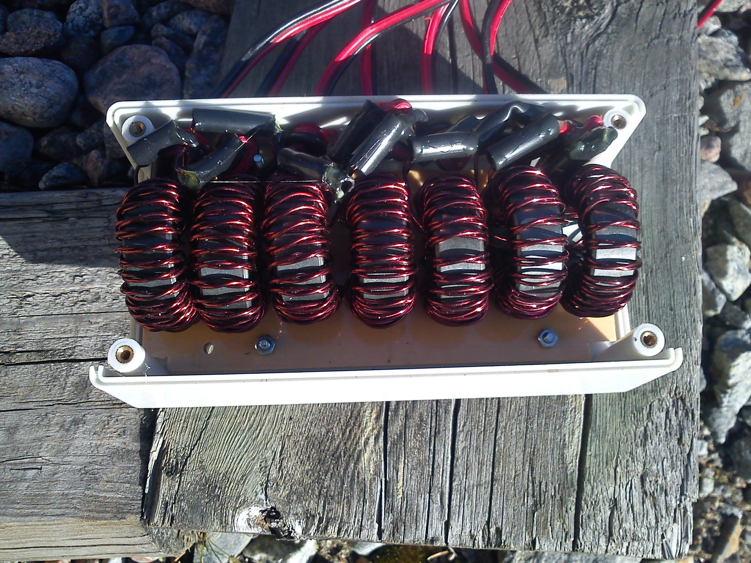
Filtret består av 7 ferritkärnor FT-140-77 lindade med ca 2×1 meter lackerad 1 mm koppartråd. En drossel för varje högtalare. Det blev ca 21 varv. Subwoofern ansluts med speciell kabel, så den får lindas på en stor FT-240-77-kärna.
Uppmätta data.
Frekvens MHz U1 Volt t-t U2 Volt t-t Dämpning dB
1,8 37 0,2 46
3,5 38 0,25 44
7,0 37 0,23 42
10,1 38 0,28 43
14,1 38 1,1 31
18,1 34 1,1 30
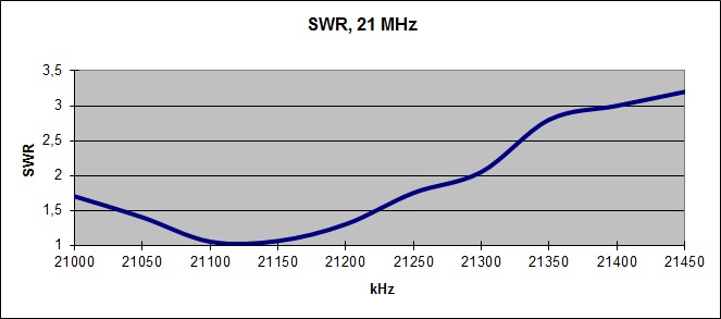
21,1 30 1,2 28
24,9 25 1,1 27
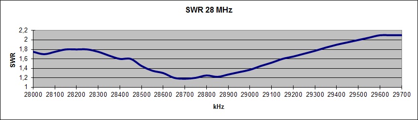
28,1 23 0,37 36
Försök gjordes för att hitta sämsta möjliga dämpning inom frekvensområdet. Det gjordes genom att variera frekvensen och belastningsimpedansen vid U2. Impedansen vid U1 hölls hela tiden till 50 ohm. Minsta dämpning uppmättes vid 25 MHz till 20 dB.
För att minimera risken för serieresonanser har även drosslar med ned till 5 varv provats, men dämpningen har över lag varit mycket sämre. Man får förmoda att förluster i kärnmaterialet är viktiga för dämpningen vilket är viktigt i den skarpa uppkopplingen i en odefinierad högtalarledning med en okänd impedans i förstärkarens utgångssteg.
Anm 1: Det visade sig senare att dämpningen av common mode-strömmar med den galvaniska skiljaren var mycket låg på kortvåg, ca 5 dB. Därför lindades en antennskarvsladd genom en ferrittoroid och seriekopplades med antennen.